 Skip to main content
A PSU can meet every voltage, current and approval requirement yet still fail earlier than expected.
One possible reason is the condition of its electrolytic capacitors. These components often influence the working life of an AC/DC PSU, especially where operating temperatures and ripple current remain high.
Electrolytic capacitors store energy, smooth rectified voltage and filter unwanted ripple. Their high capacitance and compact size make them suitable for many PSU designs.
Over time, the electrolyte inside each capacitor begins to degrade. Heat speeds up this process and can shorten the life of both the component and the PSU.
For engineers and product teams, wattage tells only part of the story. The PSU must perform reliably inside the finished product, under the real load and temperature conditions it will face.
Why Capacitor Lifetime Matters
As an electrolytic capacitor ages, its capacitance can fall and its internal resistance can rise. These changes may increase ripple, create output instability and generate more heat inside the component. Severe deterioration can lead to start-up issues, unexpected shutdowns or complete PSU failure.
Similar symptoms can appear with other faults. Ageing components, unsuitable loading and excess heat can all contribute to common power supply problems and their causes.
This overlap can make early diagnosis more difficult. Capacitor life carries greater weight in products that operate for long periods or support critical functions. Industrial controls, medical equipment, telecoms systems and security products all depend on stable long-term operation.
A single PSU fault can stop the full product from working, which makes service-life planning an important part of the design process.
What Does a Capacitor Lifetime Rating Mean?
Manufacturers rate electrolytic capacitors for a set number of hours at a stated temperature.
A typical rating may read:
5,000 hours at 105°C
This figure does not mean the capacitor will fail after exactly 5,000 hours. It shows the expected endurance of the component under defined test conditions at 105°C.
The capacitor may last much longer when it operates at a lower temperature. A common estimate suggests that service life can double for each 10°C reduction in temperature.
Example Capacitor Lifetime Rating
Using a capacitor rated for 5,000 hours at 105°C, the estimated working life may look like this:
- 105°C: 5,000 hours
- 95°C: 10,000 hours
- 85°C: 20,000 hours
- 75°C: 40,000 hours
The graph below shows how the estimated lifetime increases as the capacitor temperature falls.
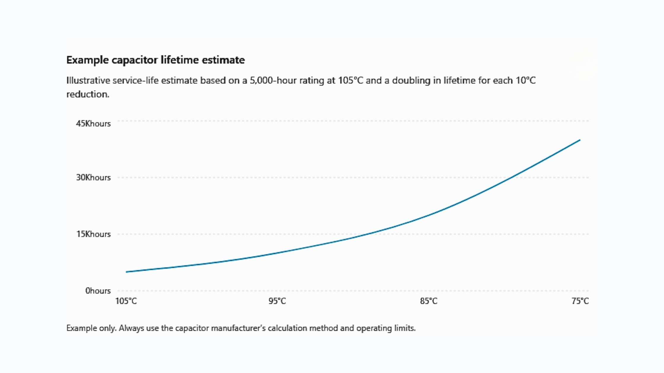
Figure: Illustrative capacitor lifetime estimate based on a 5,000-hour endurance rating at 105°C.
These values provide a simple comparison rather than a guaranteed service life. Ripple current, operating voltage, humidity, capacitor construction and daily operating conditions can change the result.
Research into aluminium electrolytic capacitor lifetime prediction highlights the effect of temperature, ripple current and operating conditions. Engineers should still use the calculation method and limits supplied for the chosen capacitor.
Heat Speeds Up Capacitor Ageing
Temperature has a major effect on electrolytic capacitor life. Higher temperatures increase the rate of electrolyte loss. As this process continues, the capacitor may struggle to maintain its original electrical performance.
The ambient temperature listed on a PSU datasheet does not always reflect the temperature reached by the internal components.
Heat may come from:
- Internal PSU losses
- Nearby processors or motors
- Switching components
- Restricted airflow
- High load levels
- Blocked ventilation
- Incorrect mounting
- A compact or sealed enclosure
A PSU may perform well during open-air testing at 25°C, then run at a much higher temperature inside the finished product. Heat from surrounding components can raise the local temperature further. A sealed enclosure may then trap this heat around the PSU and its capacitors.
Enclosure size, airflow, mounting position and output headroom should all influence your internal power supply selection.
Testing the PSU inside the final enclosure gives engineers a more realistic thermal result. Some manufacturers provide temperature measurement points for key capacitors, which can support a more accurate lifetime estimate.
Ripple Current Creates Internal Heat
Electrolytic capacitors smooth current within the rectification and switching stages of a PSU.
During this process, ripple current passes through the internal resistance of the capacitor. The resulting losses generate heat inside the component. Higher ripple current can raise the capacitor temperature and speed up ageing.
Several design factors affect the level and frequency of ripple, including:
- Converter topology
- Switching frequency
- Input conditions
- Output load
- Capacitor position
- Circuit design
Some PSU designs include active power factor correction, which adds another conversion stage to the input circuit. Each capacitor experiences different electrical and thermal stress depending on its position and purpose within the PSU.
Engineers may not have access to every internal ripple-current measurement. Lifetime curves, temperature limits and component measurement points can provide a useful alternative.
This information helps product teams judge whether a PSU can support the expected service life.
Load Level Affects PSU Temperature
A PSU running close to its maximum output will often generate more heat than the same unit operating with sensible capacity in reserve. Extra headroom can reduce thermal stress, but selecting a much larger PSU does not always solve the problem.
An oversized unit may increase cost, occupy more space and operate less efficiently at lighter loads. It may also create new mechanical or thermal challenges inside the enclosure.
Selecting the right output rating means assessing the full application, including:
- Normal operating load
- Peak and surge demand
- Start-up current
- Ambient temperature
- Cooling method
- Daily operating hours
- Efficiency across the load range
Transient loads and future product changes deserve attention too. A design that appears suitable at concept stage may have less headroom once other functions are added.
The choice between regulated and unregulated power supplies can influence voltage stability, ripple performance and behaviour under changing loads. These factors work together, so they should form part of one system-level review rather than separate datasheet checks.
Efficiency Can Reduce Thermal Stress
A PSU draws more electrical energy than it delivers to the load. The difference appears as losses, mainly in the form of heat.
Improving efficiency can reduce the heat generated inside the unit. Lower internal temperatures may then reduce stress on electrolytic capacitors and nearby components.
This matters most in:
- Compact products
- Sealed enclosures
- Fanless equipment
- Continuously operated systems
- High-temperature environments
GaN-based switching devices can reduce switching losses in suitable applications, though cost, EMC, switching frequency and thermal design still shape the final result. Efficiency should always be checked at the expected operating load.
A peak figure may occur at a different load point, so the headline specification may not reflect normal daily use.
Operating Hours Change the Result
A PSU running continuously has a different life profile from one used for eight hours each day. Product teams should review the full operating pattern rather than relying on a single temperature or load figure.
This review should include:
- Daily operating hours
- Time spent at full load
- Standby periods
- Seasonal temperature changes
- Start and stop cycles
- Planned service life
- Installation environment
- Maintenance access
A system running 24 hours a day will build up operating hours much faster than office equipment.
Temperature can change throughout the day too. High-temperature periods can accelerate capacitor ageing, even when the average daily temperature appears acceptable.
A realistic lifetime estimate should reflect both temperature and loading over time.
How to Support a Longer PSU Life
Good PSU selection starts early in the product design process.
The chosen unit needs enough output headroom for the real load, along with suitable airflow and clearance around major heat sources. Manufacturer guidance on mounting and cooling should form part of the mechanical design.
Once the first prototype is ready, test the PSU inside the final enclosure. Use the highest expected load and ambient temperature, then allow the system to reach a stable temperature before taking measurements.
A competent person should complete any testing inside an energised or open-frame PSU. They should use suitable equipment and follow safe working practices.
Useful information to request from the PSU supplier includes:
- Capacitor endurance ratings
- Maximum operating temperature
- Derating information
- Airflow requirements
- Mounting guidance
- Temperature measurement points
- Lifetime curves
- Duty-cycle assumptions
These details help engineering and sourcing teams compare PSU options against the real needs of the product.
Plan for Real Operating Conditions
Capacitor lifetime depends on more than the endurance rating printed on the datasheet. Temperature, ripple current, load, airflow and daily operating hours all affect the final result.
A realistic assessment should reflect the conditions inside the finished product. Early thermal testing and careful component selection can reduce the risk of unexpected failure later.
Use the manufacturer’s lifetime data as a starting point, then confirm performance through testing at the highest expected load and temperature. This gives engineering teams a clearer basis for judging whether the PSU can support the intended product life.
