 Skip to main content
How to Measure the Output Current of a Power Supply
Knowing how to measure output current is essential when designing, testing, or troubleshooting a power supply. Whether you’re confirming performance, checking compliance, or ensuring reliability, accurate current readings are critical.
This guide explains the key methods used to measure output current, outlines the tools involved, and highlights important safety practices. It’s written for design engineers, developers, and technical leads who need clear, practical advice.
Why Output Current Measurement Matters
Current is the rate of flow of electrical charge. Measuring it helps you understand whether your power supply is delivering the correct load.
Too much current may indicate a fault or excessive demand. Too little could point to underperformance or resistance in the circuit. Either way, unverified current can lead to downstream failures, inefficient performance, or regulatory issues.
If your product relies on stable voltage and current delivery, routine power supply current measurement should be part of your process—especially before deployment or shipment.
Method 1: Using a Multimeter to Measure Current (In Series)
The most common method for measuring current is to place a multimeter in series with the circuit. This setup allows the current to flow through the meter, enabling it to calculate and display the current in amperes.
Before starting, it’s important to break the circuit and insert the meter correctly. Always select a range that is higher than the expected current to avoid overloading or damaging the device. Use leads that are rated appropriately for the voltage and current of your circuit and ensure the resistance of the multimeter is as low as possible—this helps prevent it from affecting the accuracy of your measurement.
When set up correctly, this method is reliable, straightforward, and widely used across a range of applications.
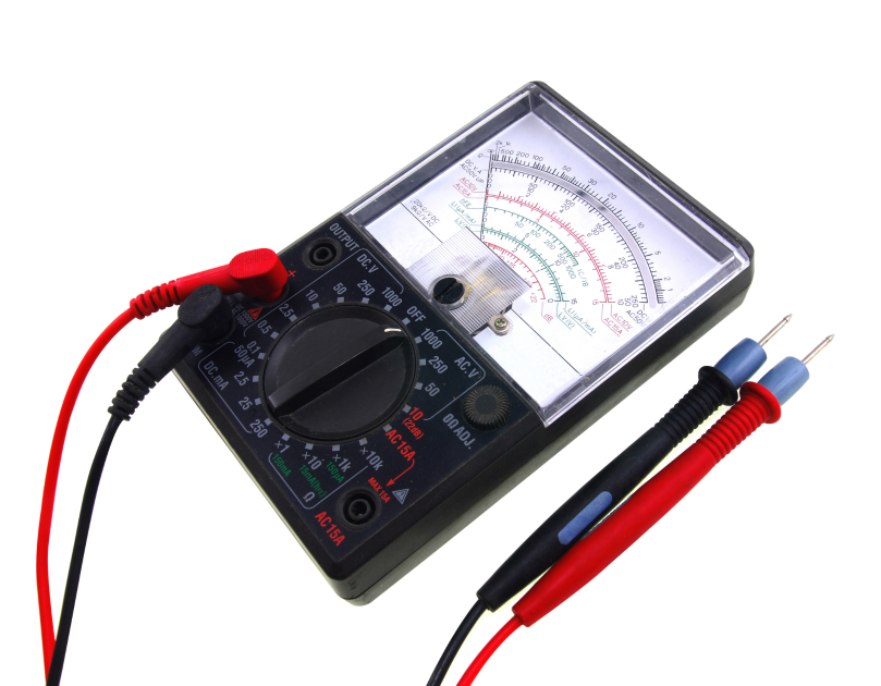
Analogue Multimeters
Analogue multimeters present readings with a moving needle over a printed scale. While not as commonly used as digital versions, they still have a place in some labs due to their simplicity and quick visual feedback.
To use an analogue multimeter for current measurement, begin by inserting the probes into the correct sockets for current. Then, set the dial to the current function and choose a range higher than your expected value.
Once the reading stabilises, you can adjust the range for more accuracy. Always return the dial to voltage mode after measuring, as leaving it set to current mode can lead to damage if it’s accidentally connected across a voltage source.
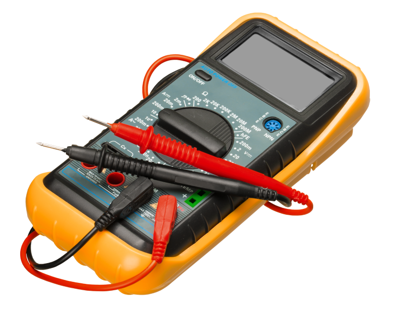
Digital Multimeters
Digital multimeters are the preferred tool for most modern applications thanks to their precision and ease of use. To measure output current, insert the black probe into the ‘COM’ socket and the red probe into the input marked for current—usually labelled A or mA. Turn the dial to the correct current range and begin with the highest setting to protect the meter.
You can step down to a more accurate range once you have a general idea of the current level. For best results, aim for a reading where the digits are active and not all zeros. This gives better accuracy and makes the data more useful in analysis.
Method 2: Using a Series Resistor
For repeated testing in a fixed circuit, placing a resistor of known value in series with the load can be a convenient and effective technique for power supply current measurement.
You measure the voltage drop across this resistor and calculate current using:
I = V / R
One of the main advantages of this technique is that it avoids the need to break the circuit every time you take a measurement. This makes it particularly useful in circuits with embedded test points or during routine development testing.
For the results to be accurate, the resistor must have a precisely known and stable value. It’s also important to ensure that the resulting voltage drop stays within safe operating limits for the equipment you’re working with.
This method is widely used in R&D labs and quality assurance environments where consistency and repeatability are key.
Method 3: Non-Intrusive Current Measurement Techniques
Breaking a circuit isn’t always practical—especially in production environments or sealed systems. That’s where current sensors come in.
Current Transformers (CTs)
Used for AC current measurement, these clamp around the conductor and produce a proportional output current or voltage. They’re safe, fast, and widely used in energy monitoring and industrial applications.
Hall Effect Sensors
Hall effect sensors are suitable for measuring both AC and DC current. These sensors detect the magnetic field generated by current flow and convert it into a signal that can be read by measuring equipment.
Their ability to monitor current without making physical contact with the conductor makes them especially useful in systems where safety or accessibility is a concern.
You’ll commonly find Hall sensors integrated into high-end digital multimeters, oscilloscopes, and custom test rigs. They are ideal for applications that require continuous current monitoring or detailed logging of current behaviour over time.
Together with current transformers, Hall sensors provide a reliable, non-intrusive way to measure output current without interrupting the circuit.
Safety: What You Need to Know
Measuring current may seem straightforward, but if done incorrectly, it poses a real risk to both equipment and personal safety. Taking a few basic precautions can significantly reduce the chance of damage or injury.
Always begin by setting the multimeter to the highest current range. This helps protect the device if the actual current exceeds expectations. Never connect a multimeter set to current mode directly across a voltage source—this can create a short circuit and cause immediate damage.
It’s also important to double-check that your meter, probes, and accessories are properly rated for the voltage and current you’re working with. Before making any changes to your test setup, disconnect power to the circuit to avoid unexpected faults or contact.
Many of Ideal Power’s internal power supplies and external PSUs are certified to IEC/EN 62368-1, making them suitable for use in regulated and safety-critical environments. For sensitive applications in audio, medical, or industrial systems, check ripple and transient current performance. Use an oscilloscope with a current probe to see this clearly. It gives a better view of what’s happening in the circuit.
Summary of Current Measurement Techniques
| Method | Use Case | Pros | Cons |
|---|---|---|---|
| Multimeter in series | General measurement | Accurate, accessible | Circuit must be broken |
| Series resistor | Repeated test points | Simple, scalable | Requires calculation |
| CT sensor | AC, non-intrusive | Safe, easy to use | AC only |
| Hall sensor | AC/DC logging | No circuit break | Needs sensor setup |
Need Help with Product-Specific Testing?
If you’re specifying a power supply or running performance validation, we’ll help you find the right solution. At Ideal Power, we support design engineers, sourcing leads and product developers with advice on specification, testing and supply.
Our team works with you to ensure your power supply performs to spec—from sourcing to delivery.
Speak to our team for technical guidance or help choosing the right AC-DC converter, DC-DC module or LED driver.